Examples of Thermal Imaging Inspection Applications
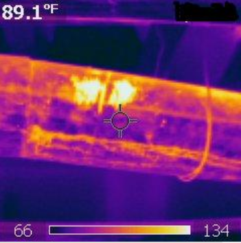
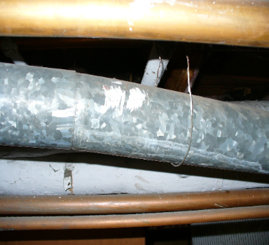
Above is a sample of the same area (visual image on the left and thermal image on the right). Looking at the visual image, nothing looks apparent, however this galvanized water heater displays a very hot area in the middle. Is this a flaw or an especially hot area on the metal? Luckily it is just some white paint accidently smudged on the pipe and it is reflecting rather than emitting infrared light.
The “Best Practices” for performing a residential infrared inspection includes:
A temperature differential (Delta-T) of at least 18 degrees F from interior to the exterior for several hours prior to the inspection. Humidity, wind speed, wind direction, sun location, recent precipitation all may affect the results from an infrared inspection.
Infrared imagery is often a grayscale picture or thermogram whose scales (or shades of color) represent the differences in emitted energy from the surface, often referred to as temperature. As a general rule, patterns in the image that are lighter in shade represent warmer temperatures; darker patterns represent cooler temperatures. Unlike visible imagery that captures visible light in the 0.4-0.7 micrometer wavelengths, objects observed using infrared imagery capture infrared wavelengths in the 8-14 micrometer range.
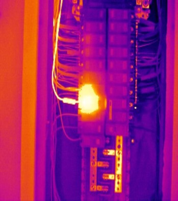
Areas that indicate faults often appear warmer due to increased load or possible arcing. Depending on conditions at the time of the inspection, such as sun exposure, wind, relative humidity, and temperature, those typically warmer patterns may be elevated in risk or potentially masked due to artifacts. Infrared imagers can detect this heat and “see” the warmer or cooler patterns, allowing the thermographer with proper training and additional tools to interpret those patterns correctly.
An HVAC system is tested with a basic temperature differential between supply and return ducts to assess the basic cooling or heating efficiency of the system. This is not a complete, detailed review, but rather a simple test to help understand if the system is performing with acceptable tolerances. If an advanced duct location test was performed within the building over a series of locations, this test would help identify areas of increased or decreased cooling, which often can be contributed to improperly sized ducts or duct leakage. Although it is not an exact science, some minimal variances between locations are normal. However, higher temperatures have been found to be a result of deficiencies within the system. Often it will be necessary to have additional testing to confirm the conditions that may be the cause of the findings. Depending on the conditions at the time of the inspection, direct sun exposure, wind, relative humidity, and temperature may impact the findings. Infrared imagers can detect and “see” the warmer or cooler patterns, allowing the thermographer with proper training and additional tools to interpret those patterns correctly.
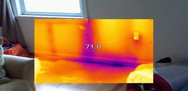
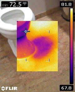
Due to evaporative cooling, areas that are wet usually appear cooler than their surrounding areas. However, depending on ambient conditions at the time of the inspection (such as sun exposure, wind, relative humidity, and temperature), typically cooler patterns or wet areas may appear warmer than their surrounding areas. Infrared imagers can detect this heat and “see” the warmer or cooler patterns, allowing the thermographer with proper training and additional tools to interpret those patterns correctly.
Areas with missing insulation most often appear lighter (warmer) during warmer days when the building’s cooling system is in use. They most often appear darker (colder) during colder days when the building’s heating system is in use. It is possible to see an anomaly that might appear as a location of missing insulation but actually indicates active moisture. It is possible to differentiate between missing insulation and active moisture by utilizing specialty tools such as moisture meters. Depending on conditions at the time of the inspection, such as sun exposure, wind, relative humidity, and temperature, patterns may reflect artifacts that appear as missing insulation. However, missing insulation usually cannot be confirmed without destructive testing, which is commonly beyond the scope of this survey. Infrared imagers can detect and “see” the warmer or cooler patterns, allowing the thermographer with proper training and additional tools to interpret those patterns correctly.
Above is a sample of the same area (visual image on the left and thermal image on the right). Looking at the visual image, nothing looks apparent, however this galvanized water heater displays a very hot area in the middle. Is this a flaw or an especially hot area on the metal? Luckily it is just some white paint accidently smudged on the pipe and it is reflecting rather than emitting infrared light.
 Call Now